Apex 7000 Belt & Gear train replacement

BELT & GEAR TRAIN REPLACEMENT INSTRUCTIONS

Rev. A 3/20/17
Document Overview
The purpose for this document is to outline specific details needed for the proper completion of preventative maintenance belt & gear train replacement.
Scope
The scope of this document is to define and layout all instructions in sequential order for the completion of preventative maintenance belt & gear train replacement process. It is the responsibility of the technician performing this procedure to follow the steps, instructions and inspection requirements as stated in this document.
Required Equipment, Tools and Supplies
Belt & Gear Train Replacement Instructions
Disassembly instructions
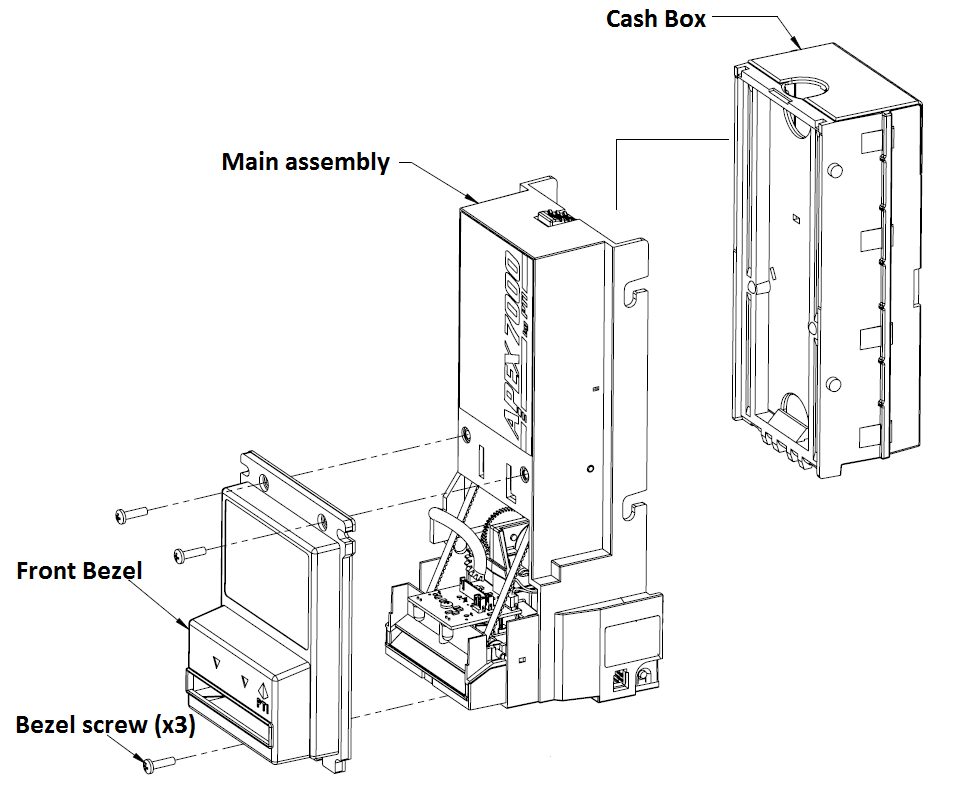
Step 1: Remove the cash box and front bezel secured with 3 screws using a #1 Philips screwdriver as indicated in the illustration below.
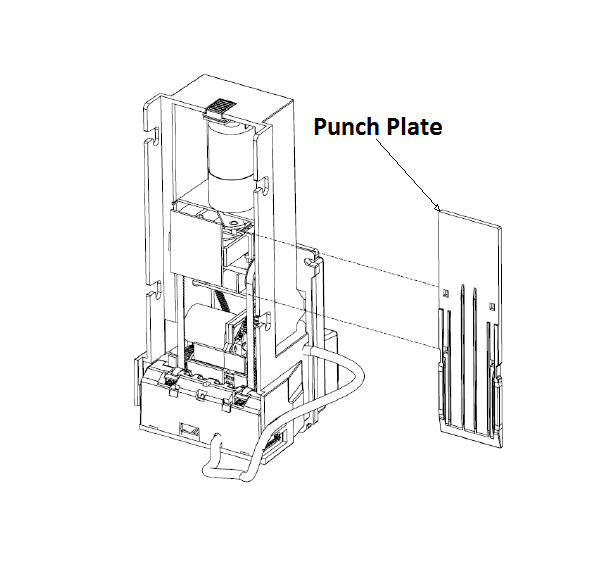
Step 2: With the cash box and bezel now removed please apply power to the unit only momentarily. This should be performed just quick enough to activate the stacker motor extending the punch plate out. After that has been achieved you can now remove the punch plate as indicated in the illustration below.
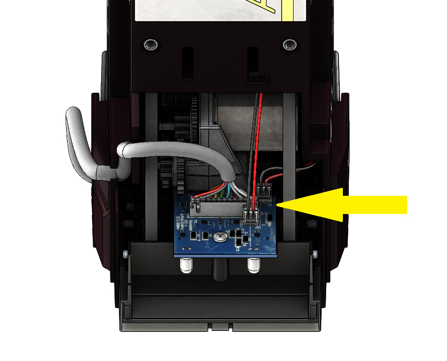
Step 3: Unplug all 3 connectors as indicated in the illustration below.
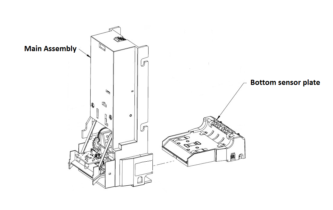
Step 4: Remove the bottom sensor plate from the main assembly as indicated in the illustration below.
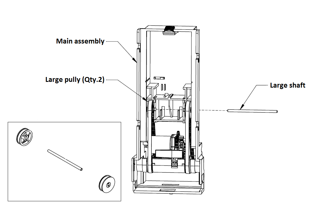
Step 5: Using your screwdriver push the large shaft out the other side a bit. Finish pulling it the rest of the way out using your needle nose pliers. With that you can then remove the large pulley assemblies and set aside, as indicated in the illustration below..
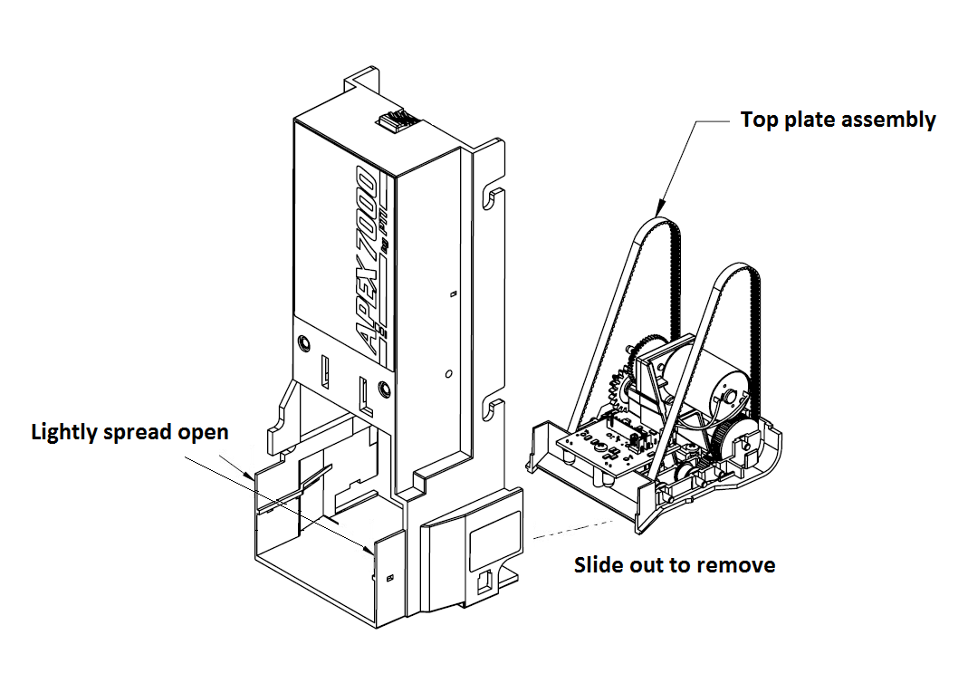
Step 5: With your fingers slightly spread apart as indicated below and remove the upper plate assembly as illustrated below.
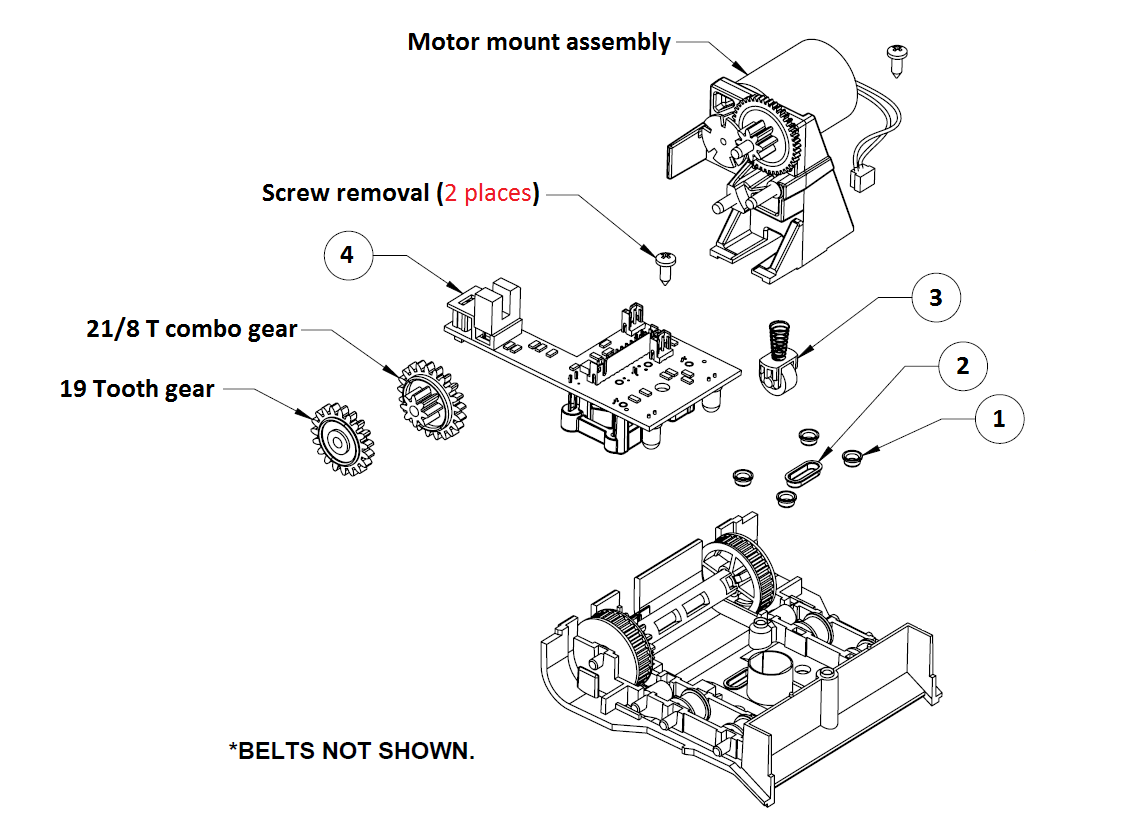
Step 6: With the upper sensor plate removed now we can begin disassembly. First remove the 2 screws as indicated. With the screws removed you can then remove the motor mount assembly, 21/8 T combo gear, 19 tooth gear and discard.
Items 1, 2 and 3 can stay in the assembly and do not need to be removed. Pay close attention that they do not fall out as they are small and can be hard to find.
Item 4 is the upper sensor board and will be used again during reassembly.
Step 7: With the motor mount assembly now removed using your needle nose pliers please remove all the metal shafts holding all pulleys and rollers in place. Once removed please discard of item number 7 (old belts) and set aside all the rest for reassembly as indicated in the illustration below.
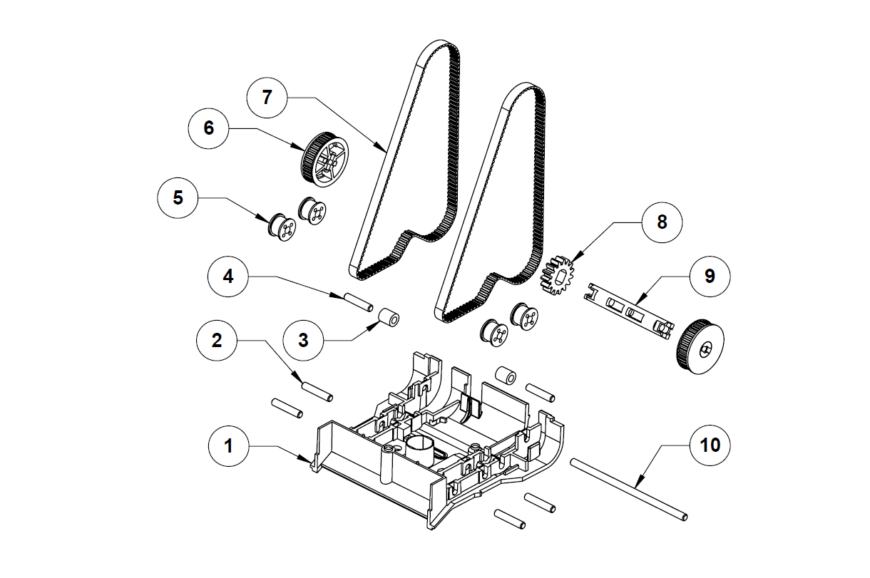
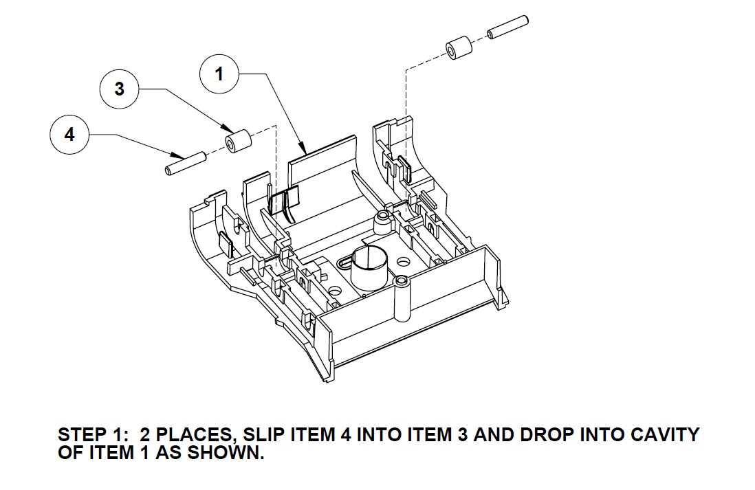
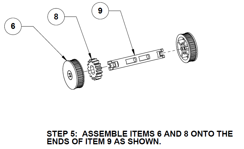
Assembly instructions Step 1: Now that disassembly is complete and the old replacement parts discarded we can begin to assemble. Please follow as indicated in the illustration below. **Note that item’s 4 are the smaller length shaft to be used. The other is longer and should not be used in this step.**
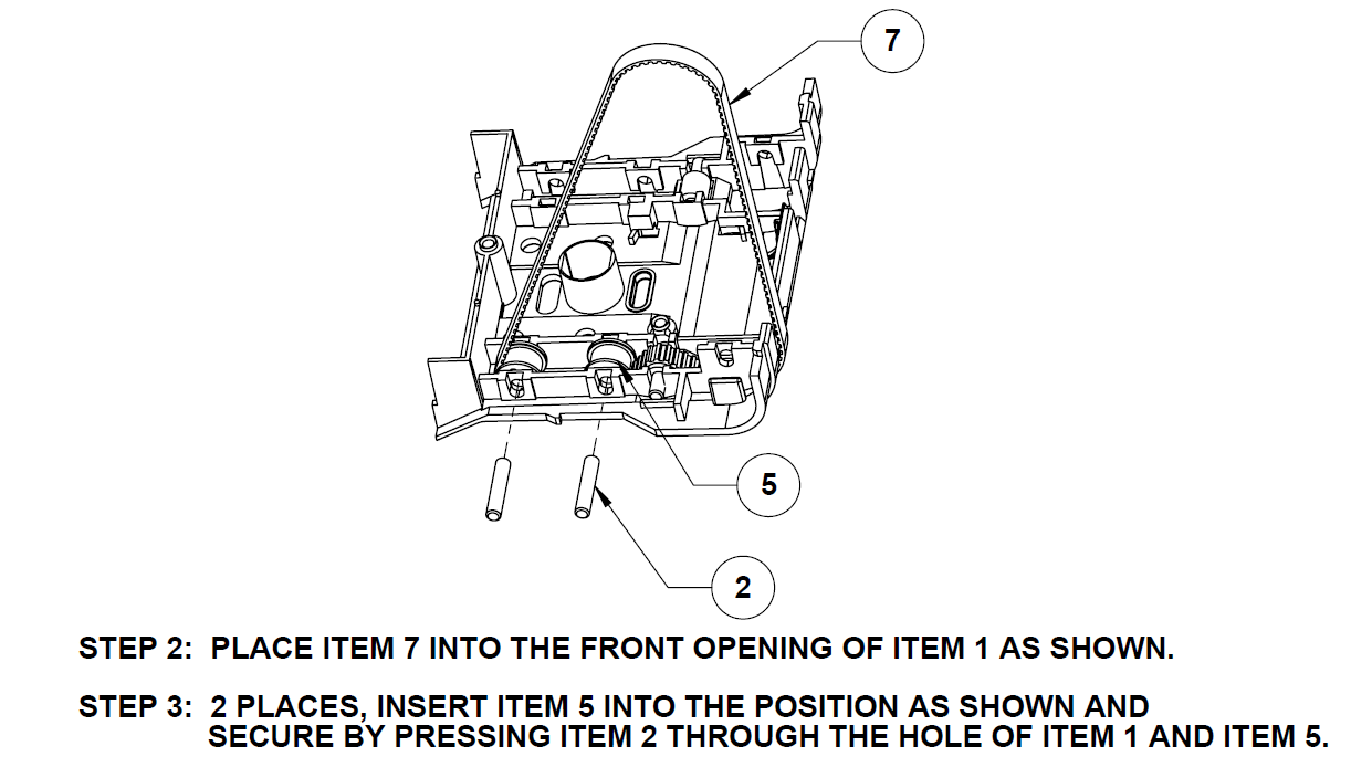
Step 5: Please follow as indicated in the illustration below.
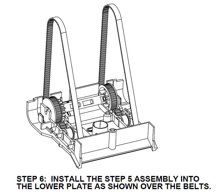
Step 6: Please follow as indicated in the illustration below.
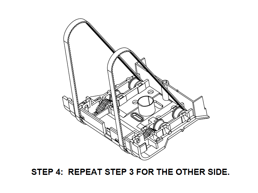
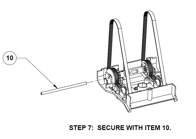
Step 7: Please follow as indicated in the illustration below.
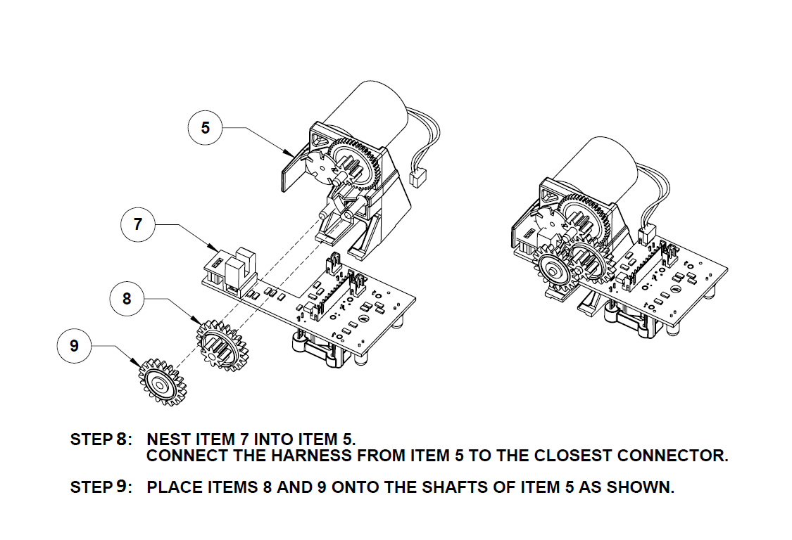
Step 8 & 9: Please follow as indicated in the illustration below.
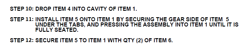
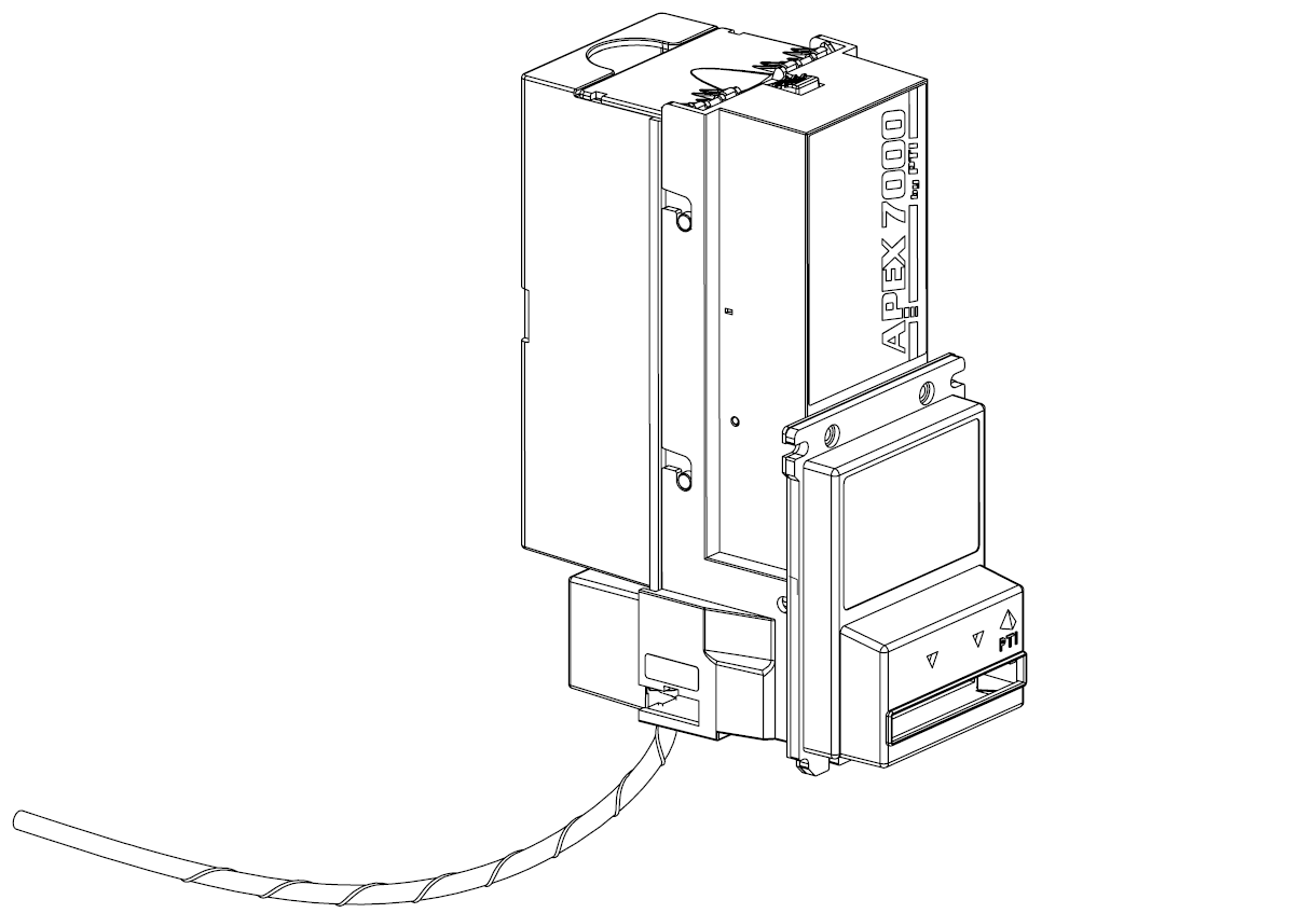
Step 10, 11 & 12: Please follow as indicated in the illustration below. Note that belts are not shown in the following illustrations.
Step 13: Please follow as indicated in the illustration below.
Step 16: Apply power to the unit only momentarily. This should be performed just quick enough to activate the stacker motor extending the punch mechanism out. After that has been achieved you can now install the punch plate as indicated in the illustration below.
Step 17: Reinstall the cash box and front bezel securing it with the 3 screws using a #1 Philips screwdriver as indicated in the illustration below.
Step 18: Assembly is now complete. Continue by performing a functional test to verify correct installation has been performed. For any issues please make sure to check that all steps have been completed as instructed for proper operation.
Related Articles
Apex 7000 Cleaning instructions
CLEANING INSTRUCTIONS www.pyramidacceptors.com Rev. A 6/27/17 Document Overview The purpose for this document is to outline specific details needed for the proper completion of preventative maintenance cleaning. Scope The scope of this document is to ...Apex 7000 Firmware Update Instructions
APEX 7000 FIRMWARE UPDATE INSTRUCTIONS www.pyramidacceptors.com Rev. A 10/30/2024 Document Overview The purpose of this document is to outline specific details needed for proper firmware updates of an Apex stacker bill acceptor. This document should ...